For normal plant shutdown, reactor power and plant output are reduced by manual insertion of control rods. After turbine load is reduced to a minimum value, steam flow is maintained through the bypass valve and the generator is disconnected from the system. Reactor power is further reduced to a low level, and the decay heat is rejected to the condenser through the turbine bypass valve. If the reactor is to be kept in the hot standby or steam condensing condition, criticality is maintained but fission power is reduced to a low level (about 0.01% of rated power is sufficient to maintain operating temperature). If refueling or other functions requiring access to the vessel are planned, all control rods are inserted and the reactor is cooled down by release of steam to the main condenser. The rate of cool down is normally controlled by periodically lowering the setting of the initial pressure regulator.

After vessel gage pressure has been reduced sufficiently 1135 psi , the heat sink can be switched from the main condenser to the RHR system heat exchangers to get the reactor to the cold shutdown condition. At some point in the process, though, the cooling system went offline; it took engineers approximately ten minutes to restore power to the cooling system. During those ten minutes, zero heat was recovered, so the temperature in the reactor began to rise. The temperature in the reactor had risen to 195°C when the cooling water was reactivated.

With the reactant flow rate tripled and the reactor operating at 195°C, the heat generated by the reaction exceeded the maximum heat removable by the cooling water. The reaction crossed the point of no return and the reactor temperature increased until rupture occurred. The reactor was equipped with an emergency pressure relief valve designed to vaporize all water within the system.

This would have removed far more than enough heat from the reactor to prevent thermal runaway. However, the pressure relief valve also failed to function and the reactor proceeded to explode approximately one hour after the cooling system failed. The three events that caused the explosion were the tripling of production, the failure of the cooling system, and the failure of the relief valve. Had any of those events not occurred, the explosion would have been prevented. The system is connected to the containment suppression pool for its supply of water for cooling and connectable to the RHR system for testing and flushing. The elevation of the pump, with respect to the minimum water level of the suppression chamber, ensures adequate net positive suction head.
The system pump is protected from overheating during operation against high reactor vessel pressure or closed injection or test valves by a low-flow bypass line to the suppression pool. A water leg pump keeps the piping between the pump and the injection valve full of water to ensure quick response and to eliminate potential hydraulic damage on system initiation. In the event of complete loss of normal electrical power, the spray system may be operated from the standby diesel generator.

Most relief valves have a poppet valve seat that is backed by a spring that opposes the gas pressure. When overpressure occurs the spring force is overcome and the excess pressure is vented. Relief valves can be used to protect components downstream of the regulator from damage, should regulator failure occur. They should be sized to handle the entire flow rate they could possibly have to vent at a pressure below the maximum pressure to which the system should be exposed.

Many relief valves, once opened by pressure, are designed to reseat when the pressure drops below the set value. Once the condition causing the relief valve to open has been corrected, the relief valve should always be checked for proper pressure setting and sealing. Relief valve outlets should always be piped into venting systems appropriate for the gas being handled. Sometimes faulty relief valves allow small amounts of process gas to pass into the vent, going undetected for long periods of time causing premature depletion of cylinder contents. Also exposure to corrosive or pyrophoric gases may cause improper relief valve operation.

Because of the critical nature of this device, it should be checked frequently for proper operation. Relief valves supplied as a part of gas delivery systems should never be relied upon to protect pressure sensitive equipment downstream from the gas delivery system. For the design of pressure-retaining systems and components, the design authority should ensure the selection of codes and standards is commensurate with the safety class and is adequate to provide confidence that plant failures are minimized.

Alternative codes and standards may be used if this would result in an equivalent or superior level of safety; justifications should be provided in such cases. The coverings and coatings for components and structures within the containment shall be carefully selected, and their methods of application shall be specified to ensure fulfillment of their safety functions. The primary objective of this requirement is to minimize interference with other safety functions or accident mitigation systems in the event of deterioration of coverings and coatings. All water-cooled nuclear power reactors shall be equipped with an emergency core cooling system . The function of this safety system is to transfer heat from the reactor core following a loss of reactor coolant that exceeds makeup capability. All equipment required for correct operation of the ECCS shall be considered part of the system or its safety support system.

To ensure the overall safety concept of defence in depth is maintained, the design shall provide multiple physical barriers to the uncontrolled release of radioactive materials to the environment. Such barriers shall include the fuel matrix, the fuel cladding, the reactor coolant pressure boundary, and the containment. The HPCS system can operate independently of normal auxiliary AC power, plant service air, or the emergency cooling water system. Operation of the system is automatically initiated from independent redundant signals indicating low reactor vessel water level or high pressure in the primary containment. The system also provides for remote-manual startup, operation, and shutdown. A testable check valve in the discharge line prevents backflow from the reactor pressure vessel when the reactor vessel pressure exceeds the HPCS system pressure such as may occur during initial activation of the system.
A low flow bypass system is placed into operation until pump head exceeds the nuclear system pressure and permits flow into the reactor vessel. A water leg pump keeps the piping between the pump and the discharge shutoff valve full of water to ensure quick response and to eliminate potential hydraulic damage on system initiation. This seal system has been demonstrated to perform without detectable leakage at all operating conditions.

These conditions include cold hydrostatic testing, heating and cooling, and power operation. Vessel supports, internal supports, their attachments, and adjacent shell sections are designed to take combined loads, including control rod drive reactions, earthquake loads, and jet reaction thrusts. The vessel is mounted on a supporting skirt, which is bolted to a concrete and steel cylindrical vessel pedestal, which is integrated with the reactor building foundation. Each nuclear power reactor shall be installed within a containment structure, so as to minimize the release of radioactive materials to the environment during operational states and DBAs. In particular, the containment and its safety features shall be able to perform their credited functions during DBAs and DECs, including melting of the reactor core.

To the extent practicable, these functions shall be available for events more severe than DECs. India is developing the Advanced Heavy Water Reactor as the third stage in its plan to utilise thorium to fuel its overall nuclear power program. The AHWR is a 300 MWe gross reactor moderated by heavy water at low pressure. The calandria has about 450 vertical pressure tubes and the coolant is pressurised light water boiling at 285ºC and circulated by convection. A large heat sink – 'gravity-driven water pool' – with 7000 cubic metres of water is near the top of the reactor building. Each fuel assembly has 30 Th-U-233 oxide pins and 24 Pu-Th oxide pins around a central rod with burnable absorber.

It is designed to be self-sustaining in relation to U-233 bred from Th-232 and have a low Pu inventory and consumption, with slightly negative void coefficient of reactivity. It is designed for 100-year plant life and is expected to utilise 65% of the energy of the fuel, with two-thirds of that energy coming from thorium via U-233. A co-located fuel cycle facility is planned, with remote handling for the highly-radioactive fresh fuel.

At the end of 2016 the design was complete and large-scale engineering studies were validating innovative features of the design. No site or construction schedule had been announced for the demonstration unit. It will use a low-speed turbine-generator and can undertake daily load-following down to 50% of power. The project was initiated in 2009 and the design was completed at the end of 2012.

In June 2012 Rosatom said it would apply for design certification in UK through Rusatom Overseas, with the VVER-TOI version. The first units are being built at Kursk II and planned for Smolensk II in Russia. Operation flexibility includes extra control rods for MOX capability, 18 to 24-month cycle, and load-following. The CAP1400 project may extend to a larger, three-loop CAP1700 or CAP2100 design if the passive cooling system can be scaled to that level. Westinghouse has agreed that SNPTC will own the intellectual property rights for any AP1000 derivatives over 1350 MWe.

Construction of the first unit at Shidaowan started without public announcement in 2019. It has a core cooling system including passive residual heat removal by convection, improved containment isolation, passive containment cooling system to the atmosphere and in-vessel retention of core damage with water cooling around it. The AP1000 gained US design certification in 2005, and UK generic design assessment approval in 2017. However, the structural design for the USA and UK was significantly modified from 2008 to withstand aircraft impact. The blowdown depressurizes the reactor vessel, permitting the operation of the LPCI function and/or the LPCS system. Blowdown is activated automatically upon coincident signals of low water level in the reactor vessel and high drywell pressure.

A time delay of approximately 2 min after receipt of the coincident signals allows the operator time to bypass the automatic blowdown if the signals are erroneous or the condition has corrected itself. The recirculation pumps take suction from the downward flow in the annulus between the core shroud and the vessel wall. Approximately one-third of the core flow is taken from the vessel through the two recirculation nozzles.

There, it is pumped at a higher pressure, distributed through a manifold to which a number of riser pipes are connected, and returned to the vessel inlet nozzles. The jet pump diffusers are welded into openings in the core shroud support shelf, which forms a barrier between the lower plenum and the suction side of the jet pump. The flow of water turns upward, where it flows between the control rod drive guide tubes and enters into the fuel support where the flow is individually directed to each fuel bundle through the nosepiece. Orifices in each fuel support piece provide the desired flow distribution among the fuel assemblies.

The coolant water passes along the individual fuel rods inside the fuel channel where it is heated and becomes a two-phase, steam–water mixture. The steam–water mixture enters a plenum located directly above the core and bounded by the separator dome, which opens to the separator array of fixed steam separators. The steam is separated from the water and passes through a dryer where any remaining water is removed. The saturated steam leaves the vessel through steam line nozzles located near the top of the vessel body end and is piped to the turbine.

Water collected in the support tray of the dryer is routed through drain lines, joins the water leaving the separators, and flows downward in the annulus between the core shroud and the vessel wall. Feedwater is added to the system through spargers located above the annulus and joins the downward flow of water. A portion of this downward flow enters the jet pumps and the remainder exits from the vessel as recirculation flow.

Three nuclear-designed butterfly valves typical of those used in domestic nuclear power plant containment purge and vent applications were tested. For a comparison of responses, two eight-inch nominal pipe size valves with differing internal design were tested. For extrapolation insights, a 24-inch nominal pipe size valve was also tested. The valve experiments were performed with various piping configurations and valve disc orientations to the flow, to simulate various installation options in field application. As a standard for comparing the effects of the installation options, testing was also performed in a standard ANSI test section.
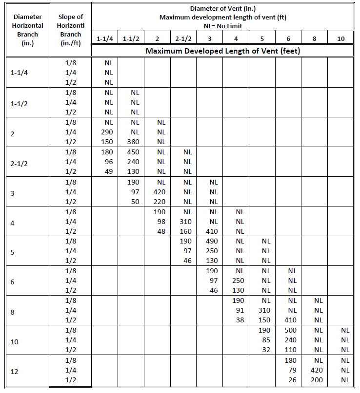
How To Calculate Reactor Size Power output from the BWR is controlled by changes in reactor water recirculation flow rate or by the moving of control rods. As the reactor power output changes, the turbine initial pressure regulator adjusts the turbine admission valve to maintain nearly constant reactor pressure, admitting the new steam flow to produce the desired change in the turbine generator power output. The BWR is operated at constant reactor pressure because pressure changes caused by turbine throttle operation in response to load changes tend to bring about reactor power changes opposite to the desired change. However, small controlled pressure changes are used to improve load response. The emergency equipment cooling system services certain equipment required for normal and emergency shutdown of the plant.

The system provides cooling water for the RHR system pump motor and pump seal cooler and the HPCS and LPCS systems pump motors and pump seal coolers. Upon loss of normal ventilation, such as may occur upon loss of external AC power, the EECS provides ventilation and cooling for the HPCS and LPCS systems, the RHR system, and the reactor core ICS equipment as required preventing overheating. Additionally, the cooling water had no reserve tanks or backup valves, so a single failure of the water line was sufficient to cause thermal runaway. A rupture disk was set to initialize the pressure relief system once the reactor pressure passed 400 psig, but the reaction was already uncontrollable before the system reached this pressure.

The runaway reaction increased the pressure in the reactor by an estimated 32,000 psi per minute, causing an immediate tank rupture and subsequent explosion. Had T2 installed redundancies within its process control system the disaster could have been prevented. Additionally, testing the reaction in an ARSST calorimeter would have informed the plant managers that as temperature and pressure increased, a second, highly exothermic side reaction occurs.

For CANDU reactors, there is a possibility of an in-core loss of coolant accident . In particular, hydraulic loads from an in-core LOCA can damage shutoff rod guides, and possibly damage poison injection nozzles. If shutdown action is required for an in-core LOCA, the design specification should identify how many reactivity devices may be damaged by the in-core LOCA. The results of the analysis of the extent of the damage and supporting experiments should be provided. Fuel damage criteria should be established for all known damage mechanisms in operational states .
The damage criteria should assure that fuel dimensions remain within operational tolerances, and that functional capabilities are not reduced below those assumed in the safety analysis. When applicable, the fuel damage criteria should consider high burnup effects based on irradiated material properties data. The nuclear system protection system initiates the rapid insertion of the control rods to shut down the reactor. The system is of the fail-safe design where it will trip on loss of electrical power but will not trip and cause a scram on the loss of a single power source. The four trip channels are physically separated from each other and from other equipment precluding the possibility of interactions that could cause possible false scrams or failure to scram.

The logic requires a manual reset by the operator, which is automatically inhibited for 10 s. Failure of a single trip channel, division logic, or a system component will not prevent the normal protective action of the nuclear system protection system. The function of the LPCS system is to prevent fuel cladding damage in the event the core is uncovered by the loss of coolant. The cooling effect is accomplished by directing jets of water down into the fuel assemblies from spray nozzles mounted in a sparger ring located above the reactor core. The system is an integral part of the total design for ECC, which provides for adequate core cooling for all rates of coolant loss from the nuclear boiler.

The system goes into operation once the reactor vessel pressure has been reduced and the operation of the other systems of the ECCS prove inadequate to maintain the necessary water level in the reactor vessel at the reduced vessel pressure. Backup auxiliary systems used during abnormal plant operation include the RCIC system, the SBLC system, the steam condensing function of the RHR system , and the suppression pool cooling function of the RHR system. ECCS consists of the LPCI function of the RHR system, the HPCS system, the LPCS system, and automatic depressurization .

The essential service water system and the area cooling systems are also required during abnormal plant operation. A shutoff valve is used in each steam line outboard of the external containment isolation valve and functions as a backup to the isolation valve. The shutoff valve is part of leakage control system to prevent possible release of nuclear steam which could leak through the main steam containment isolation valves following a LOCA.


No comments:
Post a Comment
Note: Only a member of this blog may post a comment.